
3·
12 days agoI wouldn’t know. All I am saying is that Syncthing would not work for this purpose.
I wouldn’t know. All I am saying is that Syncthing would not work for this purpose.
Syncthing works on a file level basis. If files are changed on both devices at the same time, it will have sync conflicts.

Yep, that’s the beginning of climate change scientists have warned about since ages.
Don’t worry, it will get worse in the next years.

Dude. Did you even read what I wrote? PNG is bad for photos. Your example is a photo. Go ahead and try the same with a screenshot with text and menus showing.
We can ask the same the other way around: why do you want to use jpg if it results in a bigger size and worse quality than png?
JPEG for graphics like screenshots is not very efficient. For stuff like that, png is simply superior. (But not with compression 0)
PNG is not good for photos though.
Why 0 compression?
What format are you saving them in? BMP? Try png.

Maybe you didn’t raise it enough? It is definitely the sign of being too close to the bed.
Thanks!
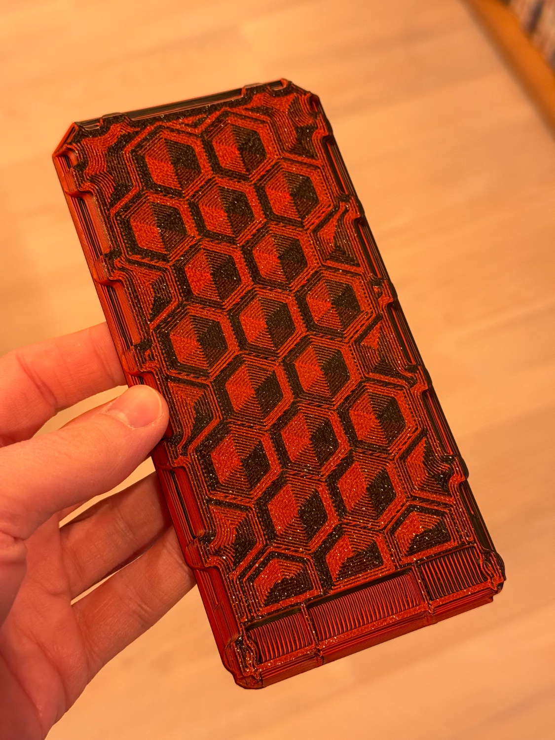
I have done something similar by purposefully adding patterns on the bottom of a 3D model.
Ok, let’s look into it. (you can also send me your printer.cfg if you want) The Mini e3 v3 has the following switchable outputs:
Keep in mind that they all switch ground only. 24V is always there.
You can use all of them for whatever you want, Klipper is very flexible here. HB is your heated bed, no questions here. E0 should be connected to your Hotted board HE0. I don’t know which of the fans on your board does what, you may need to connect them all and see which one does what (I guess your hotend does not have 3 fans). in the end you want [hotend_fan] to be the one calling the hotend (not the part!). the [fan] will be controlled by the slicer (overhangs, bridges and so on).
DCIN on your board should ideally be connected directly to the PSU, you do not want it to be switched.
don’t worry, we will get you back printing.
Glad to be of help!
The FAN1 in this case can not be controlled by software. It will always be on as soon as the printer is powered.
An exclamation mark (!) inverts a pin. The other symbol (^) enables a pull up resistor on a pin, which is needed for things like endstops or buttons. These can also be combined.
PB0 is just the name of one pin. PC0 would be a completely different pin.
Different Microcontrollers have different naming conventions, that is why you sometimes see names like PB10 and on other controllers it might be GPIO10.
See also the documentation: https://www.klipper3d.org/Config_Reference.html
The printer.cfg is highly dependent on your setup. For reference you can look at the example config for the SKR mini e3 v3: https://github.com/Klipper3d/klipper/blob/master/config/generic-bigtreetech-skr-mini-e3-v3.0.cfg
Well. Why would you want to do that?
In the end, choose the board that has the features you need. Software is the same anyway.
With Klipper you can even combine multiple boards to get the features you want.
That sound like it would wobble and easily tip over, no?
PA is also way too low (if it is even set at all). It could reduce the „thickening“ of the lines at each end dramatically.
Jokes on them, windows is and has been my secondary OS for years now. If it causes problems, I have no problems just deleting it.
A lot of companies buy it so their employees have acres to it. Like Microsoft 365 copilot for example